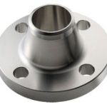
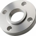
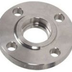
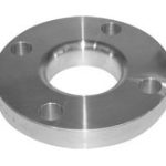
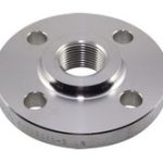
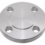
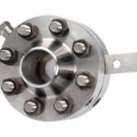
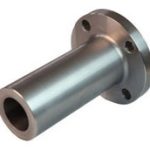
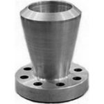
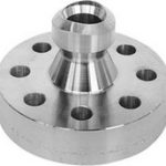
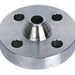
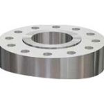
The most used flange types in Petro and chemical industry are..
Flanges General
Flanges: A flange serves as a means of connecting pipes, valves, pumps, and various equipment components to create a cohesive piping system. Beyond connectivity, it also offers convenient access for tasks such as cleaning, inspection, or modification. Typically, flanges are secured through welding or threading methods. To create flanged joints, two flanges are fastened together using bolts, with a gasket placed between them to ensure a secure seal.
Materials for Flanges
Flanges for pipes are available in a wide array of materials, including stainless steel, cast iron, aluminum, brass, bronze, plastic, and more. However, the most commonly utilized material is forged carbon steel, known for its precision-machined surfaces.
Furthermore, flanges, much like fittings and pipes designed for specific purposes, can sometimes be internally lined with materials of entirely different qualities compared to the flanges themselves. These are referred to as “lined flanges.”
The choice of flange material is often dictated by the material of the corresponding pipe. In most cases, flanges are made from the same material as the pipe they connect.
It’s worth noting that all the flanges discussed on this website adhere to the ASME and ASTM standards, unless explicitly stated otherwise. ASME B16.5 governs aspects like dimensions and dimensional tolerances, while ASTM outlines the various material qualities.
Dimensions of Flanges
Every ASME B16.5 flange adheres to a set of standardized dimensions. Whether it’s a draftsman in Japan, a work preparer in Canada, or a pipefitter in Australia, when they refer to a specific flange, such as a Welding Neck flange NPS 6, Class 150, Schedule 40 ASME B16.5, they are precisely defining the flange’s characteristics, as depicted in the image below.
When placing an order for such a flange, it’s crucial to provide information about the desired material quality. For instance, ASTM A105 designates a forged carbon steel flange, whereas A182 signifies a forged stainless steel flange.
Therefore, when submitting a correct order to a supplier, two essential standards must be clearly specified.
Bolted Flange connections
A bolted flange connection represents a sophisticated amalgamation of numerous variables, including the flange, bolts, gaskets, process conditions, temperature, pressure, and the nature of the medium being conveyed. These diverse elements are intricately interconnected, with their collective harmony being pivotal in attaining a favorable outcome.
The dependability of a flanged joint hinges significantly on the adept management of the joint fabrication process.
Product Range
PRODUCT:
WELD NECK RAISED FACE / FLAT FACE / RING TYPE JOINT (WNRF / FF / RTJ), SLIP-ON RAISED FACE / FLAT FACE / RING TYPE JOINT (SORF / FF / RTJ), BLIND RAISED FACE / FLAT FACE/RING TYPE JOINT (BLRF/FF/ RTJ) & LAP JOINT FLANGES, TONGUE AND GROOVE FLANGES & PLATE FLANGES.
SIZE:
FROM 1⁄2″ NB TO 72″ NB.
CLASS:
FROM 150# LB TO 2500# LBS, PN6 TO PN 40.
SCHEDULE:
FOR WNRF / RTJ FLANGES FROM SCH.20 TO SCH. XXS.
MATERIAL:
CARBON STEEL GRADE – A105, COPPER NICKLE 90/10, 70/30
STAINLESS STEEL GRADE-A182 F304/L, 304H, 316/L, 316H, 321 ETC.
ALLOY STEEL GRADE-A182 F1, 5, 9, 11, F22, LF2 ETC.
HIGH TENSILE GRADES – WPHY F52, 60, 65, 70 ETC.
STAINLESS STEEL GRADE-A182 F304/L, 304H, 316/L, 316H, 321 ETC.
ALLOY STEEL GRADE-A182 F1, 5, 9, 11, F22, LF2 ETC.
HIGH TENSILE GRADES – WPHY F52, 60, 65, 70 ETC.
Dimensions
Welding Neck flange
Slip On flange
Socket Weld flange
Lap Joint flange
Threaded flange
Blind flange
Orifice flange
Long Weld Neck flange
Expander flange
Nipo flange
Reducing flange
Pad flange
Welding Neck flange
Dimensions Weld Neck Flanges & Stud Bolts
ASME B16.5
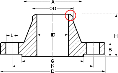
| OTHER DIA | NPS 1/2 – O.D. 21.3 | |||||
| CLass | 150 | 300 | 600 | 900 | 1500 | 2500 |
| DIA A | 30 | 38 | 38 | 38 | 38 | 43 |
| DIA D | 90 | 95 | 95 | 120 | 120 | 135 |
| THK B | 11.2 | 14.3 | 20.7 | 28.7 | 28.7 | 36.6 |
| DIA G | 35.1 | 35.1 | 35.1 | 35.1 | 35.1 | 35.1 |
| DIA K | 60.3 | 66.7 | 66.7 | 82.6 | 82.6 | 88.9 |
| H | 47.6 | 52.6 | 58.4 | 66.4 | 66.4 | 79.4 |
| NO. L | 4 | 4 | 4 | 4 | 4 | 4 |
| DIA L | 15.9 | 15.9 | 15.9 | 22.2 | 22.2 | 22.2 |
| Stud Bolts Diameter x Length | ||||||
| DIA (in) | 1/2 | 1/2 | 1/2 | 3/4 | 3/4 | 3/4 |
| lgth (mm) | 55 | 65 | 75 | 110 | 110 | 120 |
Notes..
- Dimensions are in millimeters unless otherwise indicated.
- The length of the Stud Bolt does not include the height of the chamfers (points).
- ID = Depending on the wall thickness of the pipe, must be specified by the purchaser.
- IMPORTANT! please read this short article
Dimensional Tolerances of Weld Neck Flanges ASME B16.5
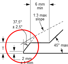
Outside Diameter *
Tolerances not listed in ASME B16.5 2013
≤24
1.6 mm (0.06 in)
>24
±3.2 mm (±0.12 in)
Tolerances not listed in ASME B16.5 2013
≤24
1.6 mm (0.06 in)
>24
±3.2 mm (±0.12 in)
Diameter Hub at Base
≤24
1.6 mm (0.06 in)
>24
±3.2 mm (±0.12 in)
≤24
1.6 mm (0.06 in)
>24
±3.2 mm (±0.12 in)
Inside Diameter
≤10
±0.8 mm (±0.03 in)
12 thru 18
1.6 mm (0.06 in)
≥20
+3.2 mm / -1.6 mm
(±0.12 in / -0.06 in)
≤10
±0.8 mm (±0.03 in)
12 thru 18
1.6 mm (0.06 in)
≥20
+3.2 mm / -1.6 mm
(±0.12 in / -0.06 in)
Diameter Hub at Point of Welding
≤5
+2.4 mm / -0.8 mm
(±0.09 in / -0.03 in)
≥6
+4.0 mm / -0.8 mm
(+0.15 in / -0.03 in)
≤5
+2.4 mm / -0.8 mm
(±0.09 in / -0.03 in)
≥6
+4.0 mm / -0.8 mm
(+0.15 in / -0.03 in)
Drilling
Bolt Circle
1.6 mm (0.06 in)
Bolt Hole Spacing
±0.8 mm (±0.03 in)
Bolt Circle
1.6 mm (0.06 in)
Bolt Hole Spacing
±0.8 mm (±0.03 in)
Eccentricity Bolt Circle
≤2.1/2
0.8 mm max (0.03 in max)
≥3
1.6 mm max (0.06 in max)
≤2.1/2
0.8 mm max (0.03 in max)
≥3
1.6 mm max (0.06 in max)
Thickness
≤18
+3.2 mm / -0 (+0.12 in / -0)
≥20
+4.8 mm / -0 (+0.18 in / -0)
≤18
+3.2 mm / -0 (+0.12 in / -0)
≥20
+4.8 mm / -0 (+0.18 in / -0)
Length thru Hub
≤10
1.6 mm (0.06 in)
≥12
±3.2 mm (±0.12 in)
≤10
1.6 mm (0.06 in)
≥12
±3.2 mm (±0.12 in)
Diameter Contact Face
1.6 mm RF (0.06 in)
±0.8 mm (±0.03 in)
6.35 mm RF (0.25 in)
±0.4 mm (±0.01 in)
1.6 mm RF (0.06 in)
±0.8 mm (±0.03 in)
6.35 mm RF (0.25 in)
±0.4 mm (±0.01 in)
Tongue and Groove
±0.4 mm (±0.01 in)
Male-Female
±0.4 mm (±0.01 in)
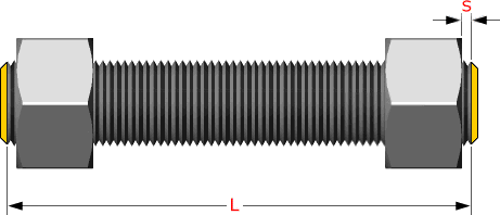
Studs are measured parallel to the axis (L) from the first to the thread without the chamfers (points). S = free threads equals 1/3 time bolt dia
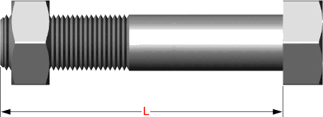
Hex bolts are measured from under the head to the top of de bolt
Slip On flange
Dimensions Slip On Flanges & Stud Bolts
ASME B16.5
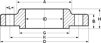
| OTHER DIA | NPS 1/2 ID 22.3 | |||||
| CLass | 150 | 300 | 600 | 900 | 1500 | 2500 |
| DIA A | 30 | 38 | 38 | 38 | 38 | … |
| DIA D | 90 | 95 | 95 | 120 | 120 | … |
| THK B | 11.2 | 14.3 | 20.7 | 28.7 | 28.7 | … |
| DIA G | 35.1 | 35.1 | 35.1 | 35.1 | 35.1 | … |
| DIA K | 60.3 | 66.7 | 66.7 | 82.6 | 82.6 | … |
| H | 15.6 | 22.6 | 28.4 | 38.4 | 38.4 | … |
| NO. L | 4 | 4 | 4 | 4 | 4 | … |
| DIA L | 15.9 | 15.9 | 15.9 | 22.2 | 22.2 | … |
| Stud Bolts Diameter x Length | ||||||
| DIA (in) | 1/2 | 1/2 | 1/2 | 3/4 | 3/4 | … |
| lgth (mm) | 55 | 65 | 75 | 110 | 110 | … |
Notes..
- Dimensions are in millimeters unless otherwise indicated.
- The length of the Stud Bolt does not include the height of the chamfers (points).
- ID = Depending on the wall thickness of the pipe, must be specified by the purchaser.
- IMPORTANT! please read this short article
Dimensional Tolerances of Weld Neck Flanges ASME B16.5
Outside Diameter *
Tolerances not listed in ASME B16.5 2013
≤24 = 1.6 mm (0.06 in)
>24 = ±3.2 mm (±0.12 in)
Tolerances not listed in ASME B16.5 2013
≤24 = 1.6 mm (0.06 in)
>24 = ±3.2 mm (±0.12 in)
Inside Diameter
≤ 10 = ± 0.8 mm
≥ 12 = + 1.6 mm / – 0 mm
≤ 10 = ± 0.8 mm
≥ 12 = + 1.6 mm / – 0 mm
Outside Diameter of Hub
≤ 12 = + 2.4 mm / – 1.6 mm
≥ 14 = ± 3.2 mm
≤ 12 = + 2.4 mm / – 1.6 mm
≥ 14 = ± 3.2 mm
Diameter of Counterbore
Same as for Inside Diameter
Same as for Inside Diameter
Drilling
Bolt Circle = 1.6 mm
Bolt Hole Spacing = ± 0.8 mm
Bolt Circle = 1.6 mm
Bolt Hole Spacing = ± 0.8 mm
Eccentricity of Bolt Circle
≤ 2.1/2 = 0.8 mm max.
≥ 3 = 1.6 mm max.
≤ 2.1/2 = 0.8 mm max.
≥ 3 = 1.6 mm max.
Thickness
≤ 18 = + 3.2 mm / – 0
≥ 20 = + 4.8 mm / – 0
≤ 18 = + 3.2 mm / – 0
≥ 20 = + 4.8 mm / – 0
Length thru Hub
≤ 18 = + 3.2 mm / – 0.8 mm
≥ 20 = + 4.8 mm / – 1.6 mm
≤ 18 = + 3.2 mm / – 0.8 mm
≥ 20 = + 4.8 mm / – 1.6 mm
Diameter of Contact Face
1.6 mm Raised Face = ± 0.8 mm
6.35 mm Raised Face
Tongue and Groove / Male-Female
± 0.4 mm
1.6 mm Raised Face = ± 0.8 mm
6.35 mm Raised Face
Tongue and Groove / Male-Female
± 0.4 mm
Studs are measured parallel to the axis (L) from the first to the thread without the chamfers (points). S = free threads equals 1/3 time bolt dia

Hex bolts are measured from under the head to the top of de bolt

Socket Weld flange
Dimensions Socket Weld Flanges & Stud Bolts
ASME B16.5
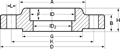
| OTHER DIA | NPS 1/2 ID=22.3 F=9.5 | |||||
| CLass | 150 | 300 | 600 | 900 | 1500 | 2500 |
| DIA A | 30 | 38 | 38 | … | 38 | … |
| DIA D | 90 | 95 | 95 | … | 120 | … |
| THK B | 11.2 | 14.3 | 20.7 | … | 28.7 | … |
| DIA G | 35.1 | 35.1 | 35.1 | … | 35.1 | … |
| DIA K | 60.3 | 66.7 | 66.7 | … | 82.6 | … |
| H | 15.6 | 22.6 | 28.4 | … | 38.4 | … |
| NO. L | 4 | 4 | 4 | … | 4 | … |
| DIA L | 15.9 | 15.9 | 15.9 | … | 22.2 | … |
| Stud Bolts Diameter x Length | ||||||
| DIA (in) | 1/2 | 1/2 | 1/2 | … | 3/4 | … |
| lgth (mm) | 55 | 65 | 75 | … | 110 | … |
Notes..
- Dimensions are in millimeters unless otherwise indicated.
- The length of the Stud Bolt does not include the height of the chamfers (points).
- ID2 = Depending on the wall thickness of the pipe, must be specified by the purchaser.
- IMPORTANT! please read this short article
Dimensional Tolerances of Socket Weld Flanges ASME B16.5
Outside Diameter *
Tolerances not listed in ASME B16.5 2013
≤ 24 = 1.6 mm
> 24 = ± 3.2 mm
Tolerances not listed in ASME B16.5 2013
≤ 24 = 1.6 mm
> 24 = ± 3.2 mm
Inside Diameter
≤ 10 = ± 0.8 mm
≥ 12 = + 1.6 mm / – 0 mm
≤ 10 = ± 0.8 mm
≥ 12 = + 1.6 mm / – 0 mm
Outside Diameter of Hub
≤ 12 = + 2.4 mm / – 1.6 mm
≥ 14 = ± 3.2 mm
≤ 12 = + 2.4 mm / – 1.6 mm
≥ 14 = ± 3.2 mm
Diameter of Counterbore
Same as for Inside Diameter
Same as for Inside Diameter
Drilling
Bolt Circle = 1.6 mm
Bolt Hole Spacing = ± 0.8 mm
Bolt Circle = 1.6 mm
Bolt Hole Spacing = ± 0.8 mm
Eccentricity of Bolt Circle
≤ 2.1/2 = 0.8 mm max.
≥ 3 = 1.6 mm max.
≤ 2.1/2 = 0.8 mm max.
≥ 3 = 1.6 mm max.
Thickness
≤ 18 = + 3.2 mm / – 0
≥ 20 = + 4.8 mm / – 0
≤ 18 = + 3.2 mm / – 0
≥ 20 = + 4.8 mm / – 0
Length thru Hub
≤ 18 = + 3.2 mm / – 0.8 mm
≥ 20 = + 4.8 mm / – 1.6 mm
≤ 18 = + 3.2 mm / – 0.8 mm
≥ 20 = + 4.8 mm / – 1.6 mm
Diameter of Contact Face
1.6 mm Raised Face = ± 0.8 mm
6.35 mm Raised Face
Tongue and Groove / Male-Female
± 0.4 mm
1.6 mm Raised Face = ± 0.8 mm
6.35 mm Raised Face
Tongue and Groove / Male-Female
± 0.4 mm
Studs are measured parallel to the axis (L) from the first to the thread without the chamfers (points). S = free threads equals 1/3 time bolt dia

Hex bolts are measured from under the head to the top of de bolt

Lap Joint flange
Dimensions Lap Joint Flanges & Stud Bolts
ASME B16.5
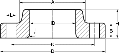
| OTHER DIA | NPS 1/2 ID=22.9 r=3 | |||||
| CLass | 150 | 300 | 600 | 900 | 1500 | 2500 |
| DIA A | 30 | 38 | 38 | 38 | 38 | 43 |
| DIA D | 90 | 95 | 95 | 120 | 120 | 135 |
| THK B | 11.2 | 14.3 | 14.3 | 22.3 | 22.3 | 30.2 |
| DIA K | 60.3 | 66.7 | 66.7 | 82.6 | 82.6 | 88.9 |
| H | 16 | 22 | 22 | 32 | 32 | 40 |
| NO. L | 4 | 4 | 4 | 4 | 4 | 4 |
| DIA L | 15.9 | 15.9 | 15.9 | 22.2 | 22.2 | 22.2 |
| Stud Bolts Diameter x Length | ||||||
| DIA (in) | 1/2 | 1/2 | 1/2 | 3/4 | 3/4 | 3/4 |
| lgth (mm) | 55 | 65 | 75 | 110 | 110 | 120 |
Notes..
- Dimensions are in millimeters unless otherwise indicated.
- The length of the Stud Bolt does not include the height of the chamfers (points).
- IMPORTANT! please read this short article
Dimensional Tolerances of Lap Joint Flanges ASME B16.5
Outside Diameter *
Tolerances not listed in ASME B16.5 2013
≤ 24 = 1.6 mm
> 24 = ± 3.2 mm
Tolerances not listed in ASME B16.5 2013
≤ 24 = 1.6 mm
> 24 = ± 3.2 mm
Inside Diameter
≤ 10 = ± 0.8 mm
≥ 12 = + 1.6 mm / – 0 mm
≤ 10 = ± 0.8 mm
≥ 12 = + 1.6 mm / – 0 mm
Outside Diameter of Hub
≤ 12 = + 2.4 mm / – 1.6 mm
≥ 14 = ± 3.2 mm
≤ 12 = + 2.4 mm / – 1.6 mm
≥ 14 = ± 3.2 mm
Diameter of Counterbore
Same as for Inside Diameter
Same as for Inside Diameter
Drilling
Bolt Circle = 1.6 mm
Bolt Hole Spacing = ± 0.8 mm
Bolt Circle = 1.6 mm
Bolt Hole Spacing = ± 0.8 mm
Eccentricity of Bolt Circle
≤ 2.1/2 = 0.8 mm max.
≥ 3 = 1.6 mm max.
≤ 2.1/2 = 0.8 mm max.
≥ 3 = 1.6 mm max.
Thickness
≤ 18 = + 3.2 mm / – 0
≥ 20 = + 4.8 mm / – 0
≤ 18 = + 3.2 mm / – 0
≥ 20 = + 4.8 mm / – 0
Length thru Hub
≤ 18 = + 3.2 mm / – 0.8 mm
≥ 20 = + 4.8 mm / – 1.6 mm
≤ 18 = + 3.2 mm / – 0.8 mm
≥ 20 = + 4.8 mm / – 1.6 mm
Diameter of Contact Face
1.6 mm Raised Face = ± 0.8 mm
6.35 mm Raised Face
Tongue and Groove / Male-Female
± 0.4 mm
1.6 mm Raised Face = ± 0.8 mm
6.35 mm Raised Face
Tongue and Groove / Male-Female
± 0.4 mm
Studs are measured parallel to the axis (L) from the first to the thread without the chamfers (points). S = free threads equals 1/3 time bolt dia

Hex bolts are measured from under the head to the top of de bolt

Threaded flange
Dimensions Threaded Flanges & Stud Bolts
ASME B16.5
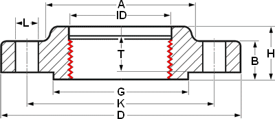
| OTHER DIA | NPS 1/2 | |||||
| CLass | 150 | 300 | 600 | 900 | 1500 | 2500 |
| DIA A | 30 | 38 | 38 | 38 | 38 | 43 |
| DIA D | 90 | 95 | 95 | 120 | 120 | 135 |
| THK B | 11.2 | 14.3 | 20.7 | 28.7 | 28.7 | 36.6 |
| DIA G | 35.1 | 35.1 | 35.1 | 35.1 | 35.1 | 35.1 |
| DIA K | 60.3 | 66.7 | 66.7 | 82.6 | 82.6 | 88.9 |
| H | 15.6 | 22.6 | 28.4 | 38.4 | 38.4 | 46.4 |
| NO. L | 4 | 4 | 4 | 4 | 4 | 4 |
| DIA L | 15.9 | 15.9 | 15.9 | 22.2 | 22.2 | 22.2 |
| Stud Bolts Diameter x Length | ||||||
| DIA (in) | 1/2 | 1/2 | 1/2 | 3/4 | 3/4 | 3/4 |
| lgth (mm) | 55 | 65 | 75 | 110 | 110 | 120 |
Notes..
- Dimensions are in millimeters unless otherwise indicated.
- The length of the Stud Bolt does not include the height of the chamfers (points).
- IMPORTANT! please read this short article
Dimensional Tolerances of Threaded Flanges ASME B16.5
Outside Diameter *
Tolerances not listed in ASME B16.5 2013
≤ 24 = 1.6 mm
> 24 = ± 3.2 mm
Tolerances not listed in ASME B16.5 2013
≤ 24 = 1.6 mm
> 24 = ± 3.2 mm
Inside Diameter
Within Limits on Boring Gauge
Within Limits on Boring Gauge
Drilling
Bolt Circle = 1.6 mm
Bolt Hole Spacing = ± 0.8 mm
Bolt Circle = 1.6 mm
Bolt Hole Spacing = ± 0.8 mm
Eccentricity of Bolt Circle
≤ 2.1/2 = 0.8 mm max.
≥ 3 = 1.6 mm max.
≤ 2.1/2 = 0.8 mm max.
≥ 3 = 1.6 mm max.
Outside Diameter of Hub
≤ 12 = + 2.4 mm / – 1.6 mm
≥ 14 = ± 3.2 mm
≤ 12 = + 2.4 mm / – 1.6 mm
≥ 14 = ± 3.2 mm
Diameter of Counterbore
Same as forInside Diameter
Same as forInside Diameter
Thickness
≤ 18 = + 3.2 mm / – 0
≥ 20 = + 4.8 mm / – 0
≤ 18 = + 3.2 mm / – 0
≥ 20 = + 4.8 mm / – 0
Length thru Hub
≤ 18 = + 3.2 mm / – 0.8 mm
≥ 20 = + 4.8 mm / – 1.6 mm
≤ 18 = + 3.2 mm / – 0.8 mm
≥ 20 = + 4.8 mm / – 1.6 mm
Diameter of Contact Face
1.6 mm Raised Face = ± 0.8 mm
6.35 mm Raised Face
Tongue and Groove / Male-Female
± 0.4 mm
1.6 mm Raised Face = ± 0.8 mm
6.35 mm Raised Face
Tongue and Groove / Male-Female
± 0.4 mm
Studs are measured parallel to the axis (L) from the first to the thread without the chamfers (points). S = free threads equals 1/3 time bolt dia

Hex bolts are measured from under the head to the top of de bolt

Blind flange
Dimensions Blind Flanges & Stud Bolts
ASME B16.5

| OTHER DIA | NPS 1/2 | |||||
| CLass | 150 | 300 | 600 | 900 | 1500 | 2500 |
| DIA D | 90 | 95 | 95 | 120 | 120 | 135 |
| B | 11.2 | 14.3 | 20.7 | 28.7 | 28.7 | 36.6 |
| DIA G | 35.1 | 35.1 | 35.1 | 35.1 | 35.1 | 35.1 |
| DIA K | 60.3 | 66.7 | 66.7 | 82.6 | 82.6 | 88.9 |
| NO. L | 4 | 4 | 4 | 4 | 4 | 4 |
| DIA L | 15.9 | 15.9 | 15.9 | 22.2 | 22.2 | 22.2 |
| Stud Bolts Diameter x Length | ||||||
| DIA (in) | 1/2 | 1/2 | 1/2 | 3/4 | 3/4 | 3/4 |
| lgth (mm) | 55 | 65 | 75 | 110 | 110 | 120 |
Notes..
- Dimensions are in millimeters unless otherwise indicated.
- The length of the Stud Bolt does not include the height of the chamfers (points).
- IMPORTANT! please read this short article
Dimensional Tolerances of Blind Flanges ASME B16.5
Outside Diameter *
Tolerances not listed in ASME B16.5 2013
≤ 24 = 1.6 mm
> 24 = ± 3.2 mm
Tolerances not listed in ASME B16.5 2013
≤ 24 = 1.6 mm
> 24 = ± 3.2 mm
Inside Diameter
not applicable
not applicable
Outside Diameter of Hub
≤ 12 = + 2.4 mm / – 1.6 mm
≥ 14 = ± 3.2 mm
≤ 12 = + 2.4 mm / – 1.6 mm
≥ 14 = ± 3.2 mm
Outside Diameter of Hub
≤ 12 = + 2.4 mm / – 1.6 mm
≥ 14 = ± 3.2 mm
≤ 12 = + 2.4 mm / – 1.6 mm
≥ 14 = ± 3.2 mm
Drilling
Bolt Circle = 1.6 mm
Bolt Hole Spacing = ± 0.8 mm
Bolt Circle = 1.6 mm
Bolt Hole Spacing = ± 0.8 mm
Eccentricity of Bolt Circle
≤ 2.1/2 = 0.8 mm max.
≥ 3 = 1.6 mm max.
≤ 2.1/2 = 0.8 mm max.
≥ 3 = 1.6 mm max.
Thickness
≤ 18 = + 3.2 mm / – 0
≥ 20 = + 4.8 mm / – 0
≤ 18 = + 3.2 mm / – 0
≥ 20 = + 4.8 mm / – 0
Length thru Hub
≤ 18 = + 3.2 mm / – 0.8 mm
≥ 20 = + 4.8 mm / – 1.6 mm
≤ 18 = + 3.2 mm / – 0.8 mm
≥ 20 = + 4.8 mm / – 1.6 mm
Diameter of Contact Face
1.6 mm Raised Face = ± 0.8 mm
6.35 mm Raised Face
Tongue and Groove / Male-Female ± 0.4 mm
1.6 mm Raised Face = ± 0.8 mm
6.35 mm Raised Face
Tongue and Groove / Male-Female ± 0.4 mm
Studs are measured parallel to the axis (L) from the first to the thread without the chamfers (points). S = free threads equals 1/3 time bolt dia

Hex bolts are measured from under the head to the top of de bolt

Orifice flange
Long Weld Neck flange
Expander flange
Nipo flange
Reducing flange
Pad flange


