Fittings for Socket Weld Pipe systems
Definition and Details of Socket Weld Fittings ASME B16.11
A socket weld represents a pipe connection method in which a pipe is inserted into a recessed area of a valve, fitting, or flange. Unlike butt-welded fittings, socket-welded fittings find their primary application in scenarios involving smaller pipe diameters, typically for pipes with a nominal diameter of NPS 2 or smaller.
For connecting pipes to valves, fittings, or other pipe segments, the use of fillet-type seal welds is recommended. Socket-welded joint construction serves as an excellent choice wherever the advantages of high leak resistance and strong structural integrity hold significance in the design.
While fatigue resistance may not be as robust as in butt-welded construction due to the utilization of fillet welds and the presence of abrupt fitting geometry, it still surpasses that of most mechanical joining methods.
Some details of Socket Weld fittings
SW Fittings constitute a versatile family of high-pressure fittings utilized across a spectrum of industrial applications.
- SW Fittings constitute a versatile family of high-pressure fittings utilized across a spectrum of industrial applications.
- These fittings serve as the ideal choice for pipelines carrying substances that are flammable, toxic, or of high value, where even the slightest leakage is unacceptable. Moreover, they find their purpose in steam systems operating within the pressure range of 300 to 600 PSI.
- To ensure compatibility, SW fittings are exclusively employed in conjunction with ASME pipe and are readily available in a matching size range. They are most commonly employed in scenarios where pipework is intended to be permanent, and their design emphasizes the facilitation of optimal flow characteristics.
- In line with stringent quality standards, these fittings are crafted to conform to multiple ASTM specifications and are meticulously manufactured in accordance with ASME B16.11 guidelines. The B16.11 standard comprehensively addresses pressure-temperature ratings, dimensions, tolerances, marking, and material requisites for forged carbon and alloy steel fittings. The acceptable material forms for these fittings include forgings, bars, seamless pipes, and seamless tubes that adhere to the chemical composition, melting processes, and mechanical property prerequisites outlined in ASTM A105, A182, or A350.
- SW Fittings are available in three distinct pressure ratings: Class 3000, 6000, and 9000.
Advantages and Disadvantages of Socket Weld fittings
Advantages
- The necessity of beveling the pipe in preparation for welding is rendered redundant.
- Temporary tack welding to achieve alignment is rendered unnecessary, as the fitting inherently ensures proper alignment.
- The weld metal is incapable of infiltrating the pipe’s bore.
- These fittings can serve as substitutes for threaded fittings, substantially reducing the risk of leakage.
- Due to practical constraints, radiography cannot be employed for inspecting the fillet weld. Consequently, precise fitting and welding assume paramount importance. The fillet weld may be subject to scrutiny through surface examination, magnetic particle (MP) testing, or liquid penetrant (PT) examination methods.
- Construction expenses are diminished in comparison to butt-welded joints, primarily due to the absence of exacting fit-up requirements and the elimination of specialized machining for butt-weld end preparation.
Disadvantages
- To ensure proper socket weld assembly, welders must maintain a 1/16 inch (1.6 mm) expansion gap between the pipe and the socket shoulder, as specified in ASME B31.1 para. 127.3 Preparation for Welding (E) Socket Weld Assembly.
- The assembly process stipulates that during the joint’s pre-welding stage, the pipe or tube should be inserted into the socket to its maximum depth and then retracted by approximately 1/16 (1.6 mm) to create a gap between the end of the pipe and the socket’s shoulder.
- Socket-welded systems, due to the presence of expansion gaps and internal crevices, are susceptible to corrosion, making them less suitable for applications involving corrosive or radioactive substances. The accumulation of solids at these joints can lead to operational and maintenance issues, necessitating butt welds with complete penetration into the interior of the piping across all pipe sizes.
- In ultrahigh hydrostatic pressure (UHP) applications within the food industry, socket welding is deemed unacceptable. This method does not allow for full penetration and leaves behind overlaps and crevices that are exceedingly difficult to clean, resulting in potential virtual leaks.
The primary objective of incorporating bottoming clearance in a socket weld is typically twofold:
- Mitigating residual stress: This clearance helps minimize the formation of residual stress at the weld’s root, which may arise during the solidification of the weld metal.
- Accommodating Differential Expansion: It also facilitates the accommodation of any differential expansion that may occur between the mating elements.
Product Range
PRODUCT:
ELBOW 90 & 45 DEG., EQUAL & UNEQUAL TEE, CONCENTRIC & ECCENTRIC REDUCER, CAP, UNION, SOCKET, STUB END, SWAGE NIPPLE, FULL & HALF COUPLING, WELDOLET, THREADOLET, ELBOWLET, SOCKOLET, C ROSS
SIZE:
FROM 3/4″ NB TO 4″ NB.
CLASS:
FROM 2000# TO 9000#.
DIMENSION:
ASME / ANSI B16.11
MATERIAL:
CARBON STEEL GRADE-A105, COPPER NICKLE 90/10, 70/30
STAINLESS STEEL GRADE – A182 F304/L, 304H, 316/L, 316H, 321 ETC.
ALLOY STEEL GRADE – A182 F1, 5, 9, 11, F22, LF2 ETC.
COPPER NICKLE GRADE 90/10, 70/30.
HIGH TENSILE GRADES – WPHY F52, 60, 65, 70 ETC.
STAINLESS STEEL GRADE – A182 F304/L, 304H, 316/L, 316H, 321 ETC.
ALLOY STEEL GRADE – A182 F1, 5, 9, 11, F22, LF2 ETC.
COPPER NICKLE GRADE 90/10, 70/30.
HIGH TENSILE GRADES – WPHY F52, 60, 65, 70 ETC.
Dimensions
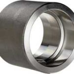
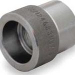
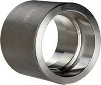
Full-coupling
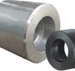
Half-coupling
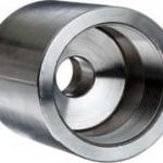
Reducing coupling
Reducer insert
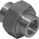
Union (MSS SP-83)
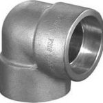
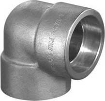
Elbow 90°
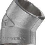
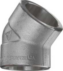
Elbow 45°
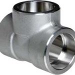
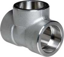
Tee Straight
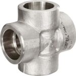
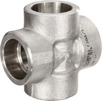
Cross
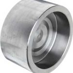
Cap (End Cap)
Full-coupling
Dimensions Socket Weld Couplings
ASME B16.11
Class 3000 |
||||
| NPS | Socket Bore | Depth Socket | Bore DIA | Socket wall THK |
| B | J | D | C | |
| 1/2 | 21.95 21.70 |
10 | 16.6 15 |
4.65 4.10 |
| 3/4 | 27.30 27.05 |
13 | 21.7 20.2 |
4.90 4.25 |
| 1 | 34.05 33.80 |
13 | 27.4 25.9 |
5.70 5.00 |
| 1.1/4 | 42.80 42.55 |
13 | 35.8 34.3 |
6.05 5.30 |
| 1.1/2 | 48.90 48.65 |
13 | 41.7 40.1 |
6.35 5.55 |
| 2 | 61.35 61.10 |
16 | 53.5 51.7 |
6.95 6.05 |
| 2.1/2 | 74.20 73.80 |
16 | 64.2 61.2 |
8.75 7.65 |
| 3 | 90.15 89.80 |
16 | 79.5 46.4 |
9.50 8.30 |
| 4 | 115.80 115.45 |
19 | 103.8 100.7 |
10.70 9.35 |
| NPS | Laying lengths | |||
| Coupling E |
Half coupling F |
|||
| 1/2 | 9.5 | 22.5 | ||
| 3/4 | 9.5 | 23.5 | ||
| 1 | 13 | 29 | ||
| 1.1/4 | 13 | 30 | ||
| 1.1/2 | 13 | 32 | ||
| 2 | 19 | 41 | ||
| 2.1/2 | 19 | 42.5 | ||
| 3 | 19 | 44.5 | ||
| 4 | 19 | 47.5 | ||
Class 6000 |
||||
| NPS | Socket Bore | Depth Socket | Bore DIA | Socket wall THK |
| B | J | D | C | |
| 1/2 | 21.95 21.70 |
10 | 12.5 11 |
5.95 5.20 |
| 3/4 | 27.30 27.05 |
13 | 16.3 14.8 |
6.95 6.05 |
| 1 | 34.05 33.80 |
13 | 21.5 19.9 |
7.90 6.95 |
| 1.1/4 | 42.80 42.55 |
13 | 30.2 28.7 |
7.90 6.95 |
| 1.1/2 | 48.90 48.65 |
13 | 34.7 33.2 |
8.90 7.80 |
| 2 | 61.35 61.10 |
16 | 43.6 42.1 |
10.90 9.50 |
| NPS | Laying lengths | |||
| Coupling E |
Half coupling F |
|||
| 1/2 | 9.5 | 22.5 | ||
| 3/4 | 9.5 | 23.5 | ||
| 1 | 13 | 29 | ||
| 1.1/4 | 13 | 30 | ||
| 1.1/2 | 13 | 32 | ||
| 2 | 19 | 41 | ||
General notes..
- Dimensions are in millimeters unless otherwise indicated.
- Socket Bore (B) – Maximum and Minimum dimensions.
- Bore Diameter (D) – Maximum and Minimum dimensions.
- Socket wall thickness – (C) – Average of Socket wall thickness.
- Dimensional tolerances laying lengths – (E & F)
NPS 1/2 and NPS 3/4 = +/- 1.5 mm
NPS 1 to NPS 2 = +/- 2 mm
NPS 2.1/2 to NPS 4 = +/- 2.5 mm
Half-coupling
Dimensions Socket Weld Couplings
ASME B16.11
Class 3000 |
||||
| NPS | Socket Bore | Depth Socket | Bore DIA | Socket wall THK |
| B | J | D | C | |
| 1/2 | 21.95 21.70 |
10 | 16.6 15 |
4.65 4.10 |
| 3/4 | 27.30 27.05 |
13 | 21.7 20.2 |
4.90 4.25 |
| 1 | 34.05 33.80 |
13 | 27.4 25.9 |
5.70 5.00 |
| 1.1/4 | 42.80 42.55 |
13 | 35.8 34.3 |
6.05 5.30 |
| 1.1/2 | 48.90 48.65 |
13 | 41.7 40.1 |
6.35 5.55 |
| 2 | 61.35 61.10 |
16 | 53.5 51.7 |
6.95 6.05 |
| 2.1/2 | 74.20 73.80 |
16 | 64.2 61.2 |
8.75 7.65 |
| 3 | 90.15 89.80 |
16 | 79.5 46.4 |
9.50 8.30 |
| 4 | 115.80 115.45 |
19 | 103.8 100.7 |
10.70 9.35 |
| NPS | Laying lengths | |||
| Coupling E |
Half coupling F |
|||
| 1/2 | 9.5 | 22.5 | ||
| 3/4 | 9.5 | 23.5 | ||
| 1 | 13 | 29 | ||
| 1.1/4 | 13 | 30 | ||
| 1.1/2 | 13 | 32 | ||
| 2 | 19 | 41 | ||
| 2.1/2 | 19 | 42.5 | ||
| 3 | 19 | 44.5 | ||
| 4 | 19 | 47.5 | ||
Class 6000 |
||||
| NPS | Socket Bore | Depth Socket | Bore DIA | Socket wall THK |
| B | J | D | C | |
| 1/2 | 21.95 21.70 |
10 | 12.5 11 |
5.95 5.20 |
| 3/4 | 27.30 27.05 |
13 | 16.3 14.8 |
6.95 6.05 |
| 1 | 34.05 33.80 |
13 | 21.5 19.9 |
7.90 6.95 |
| 1.1/4 | 42.80 42.55 |
13 | 30.2 28.7 |
7.90 6.95 |
| 1.1/2 | 48.90 48.65 |
13 | 34.7 33.2 |
8.90 7.80 |
| 2 | 61.35 61.10 |
16 | 43.6 42.1 |
10.90 9.50 |
| NPS | Laying lengths | |||
| Coupling E |
Half coupling F |
|||
| 1/2 | 9.5 | 22.5 | ||
| 3/4 | 9.5 | 23.5 | ||
| 1 | 13 | 29 | ||
| 1.1/4 | 13 | 30 | ||
| 1.1/2 | 13 | 32 | ||
| 2 | 19 | 41 | ||
General notes..
- Dimensions are in millimeters unless otherwise indicated.
- Socket Bore (B) – Maximum and Minimum dimensions.
- Bore Diameter (D) – Maximum and Minimum dimensions.
- Socket wall thickness – (C) – Average of Socket wall thickness.
- Dimensional tolerances laying lengths – (E & F)
NPS 1/2 and NPS 3/4 = +/- 1.5 mm
NPS 1 to NPS 2 = +/- 2 mm
NPS 2.1/2 to NPS 4 = +/- 2.5 mm
Reducing coupling
Dimensions Socket Weld Reducing Couplings
ASME B16.11
Class 3000 |
|||||||
| NPS | Socket Bore | Depth Socket J |
Bore dia | ||||
| B1 | B2 | B1 | B2 | D | |||
| 3/4 1/2 |
27.30 27.05 |
21.95 21.70 |
13 | 10 | 16.6 15 |
||
| 1 3/4 |
34.05 33.80 |
27.30 27.05 |
13 | 13 | 21.7 20.2 |
||
| 1 1/2 |
34.05 33.80 |
21.95 21.70 |
13 | 10 | 16.6 15 |
||
| 1.1/4 1 |
42.80 42.55 |
34.05 33.80 |
13 | 13 | 27.4 25.9 |
||
| 1.1/2 1 |
48.90 48.65 |
34.05 33.80 |
13 | 13 | 27.4 25.9 |
||
| 1.1/2 3/4 |
48.90 48.65 |
27.30 27.05 |
13 | 13 | 21.7 20.2 |
||
| 1.1/2 1/2 |
48.90 48.65 |
21.95 21.70 |
13 | 10 | 16.6 15 |
||
| 2 1.1/2 |
61.35 61.10 |
48.90 48.65 |
16 | 13 | 41.7 40.1 |
||
| 2 1 |
74.20 73.80 |
34.05 33.80 |
16 | 13 | 27.4 25.9 |
||
| NPS | Length Coupling | Diameter Coupling |
|||||
| Q | R | ||||||
| 3/4 1/2 |
35 | 36 | |||||
| 1 3/4 |
38.1 | 45.2 | |||||
| 1 1/2 |
38.1 | 45.2 | |||||
| 1.1/4 1 |
38.1 | 55.1 | |||||
| 1.1/2 1 |
38.1 | 60 | |||||
| 1.1/2 3/4 |
38.1 | 60 | |||||
| 1.1/2 1/2 |
38.1 | 60 | |||||
| 2 1.1/2 |
51.3 | 74.9 | |||||
| 2 1 |
51.3 | 74.9 | |||||
Class 6000 |
|||||||
| NPS | Socket Bore | Depth Socket J |
Bore dia | ||||
| B1 | B2 | B1 | B2 | D | |||
| 3/4 1/2 |
27.30 27.05 |
21.95 21.70 |
13 | 10 | 12.5 11 |
||
| 1 3/4 |
34.05 33.80 |
27.30 27.05 |
13 | 13 | 16.3 14.8 |
||
| 1 1/2 |
34.05 33.80 |
21.95 21.70 |
13 | 10 | 12.5 11 |
||
| 1.1/4 1 |
42.80 42.55 |
34.05 33.80 |
13 | 13 | 21.5 19.9 |
||
| 1.1/2 1 |
48.90 48.65 |
34.05 33.80 |
13 | 13 | 21.5 19.9 |
||
| 1.1/2 3/4 |
48.90 48.65 |
27.30 27.05 |
13 | 13 | 16.3 14.8 |
||
| 1.1/2 1/2 |
48.90 48.65 |
21.95 21.70 |
13 | 10 | 12.5 11 |
||
| 2 1.1/2 |
61.35 61.10 |
48.90 48.65 |
16 | 13 | 34.7 33.2 |
||
| 2 1 |
74.20 73.80 |
34.05 33.80 |
16 | 13 | 21.5 19.9 |
||
| NPS | Length Coupling | Diameter Coupling |
|||||
| Q | R | ||||||
| 3/4 1/2 |
35 | 40.1 | |||||
| 1 3/4 |
38.1 | 50 | |||||
| 1 1/2 |
38.1 | 50 | |||||
| 1.1/4 1 |
38.1 | 57.9 | |||||
| 1.1/2 1 |
38.1 | 65 | |||||
| 1.1/2 3/4 |
38.1 | 65 | |||||
| 1.1/2 1/2 |
38.1 | 65 | |||||
| 2 1.1/2 |
51.3 | 82 | |||||
| 2 1 |
51.3 | 82 | |||||
General notes..
- Dimensions are in millimeters unless otherwise indicated.
- Socket Bore (B1 / B2) – Maximum and Minimum dimensions.
- Bore Diameter (D) – Maximum and Minimum dimensions.
Reducer insert
Union (MSS SP-83)
Elbow 90°
Dimensions Socket Weld Elbows
ASME B16.11
Class 3000 |
|||||
| NPS | Socket Bore | Depth Socket | Bore DIA | Socket WT | Body WT |
| B | J | D | C | G | |
| 1/2 | 21.95 21.70 |
10 | 16.6 15 |
4.65 4.10 |
3.75 |
| 3/4 | 27.30 27.05 |
13 | 21.7 20.2 |
4.90 4.25 |
3.90 |
| 1 | 34.05 33.80 |
13 | 27.4 25.9 |
5.70 5.00 |
4.55 |
| 1.1/4 | 42.80 42.55 |
13 | 35.8 34.3 |
6.05 5.30 |
4.85 |
| 1.1/2 | 48.90 48.65 |
13 | 41.7 40.1 |
6.35 5.55 |
5.10 |
| 2 | 61.35 61.10 |
16 | 53.5 51.7 |
6.95 6.05 |
5.55 |
| 2.1/2 | 74.20 73.80 |
16 | 64.2 61.2 |
8.75 7.65 |
7.00 |
| 3 | 90.15 89.80 |
16 | 79.5 46.4 |
9.50 8.30 |
7.60 |
| 4 | 115.80 115.45 |
19 | 103.8 100.7 |
10.70 9.35 |
8.55 |
| NPS | Center to bottom of socket A |
||||
| 90° | 45° | ||||
| 1/2 | 15.5 | 11.5 | |||
| 3/4 | 19.5 | 12.5 | |||
| 1 | 22 | 14 | |||
| 1.1/4 | 27 | 17 | |||
| 1.1/2 | 32 | 21 | |||
| 2 | 38 | 25 | |||
| 2.1/2 | 41.5 | 29 | |||
| 3 | 57.5 | 31.5 | |||
| 4 | 66.5 | 41.5 | |||
Class 6000 |
|||||
| NPS | Socket Bore | Depth Socket | Bore DIA | Socket WT | Body WT |
| B | J | D | C | G | |
| 1/2 | 21.95 21.70 |
10 | 12.5 11 |
5.95 5.20 |
4.80 |
| 3/4 | 27.30 27.05 |
13 | 16.3 14.8 |
6.95 6.05 |
5.55 |
| 1 | 34.05 33.80 |
13 | 21.5 19.9 |
7.90 6.95 |
6.35 |
| 1.1/4 | 42.80 42.55 |
13 | 30.2 28.7 |
7.90 6.95 |
6.35 |
| 1.1/2 | 48.90 48.65 |
13 | 34.7 33.2 |
8.90 7.80 |
7.15 |
| 2 | 61.35 61.10 |
16 | 43.6 42.1 |
10.90 9.50 |
8.75 |
| NPS | Center to bottom of socket A |
||||
| 90° | 45° | ||||
| 1/2 | 19.5 | 12.5 | |||
| 3/4 | 22.5 | 14.5 | |||
| 1 | 27 | 17 | |||
| 1.1/4 | 32 | 21 | |||
| 1.1/2 | 38 | 25 | |||
| 2 | 41 | 29 | |||
General notes..
- Dimensions are in millimeters unless otherwise indicated.
- Socket Bore (B) – Maximum and minimum dimensions.
- Bore Diameter (D) – Maximum and minimum dimensions.
- Socket wall thickness – (C) – Average of Socket wall thickness.
- Dimensional tolerances center to bottom of socket – (A)
NPS 1/2 and NPS 3/4 = +/- 1.5 mm
NPS 1 to NPS 2 = +/- 2 mm
NPS 2.1/2 to NPS 4 = +/- 2.5 mm
Elbow 45°
Dimensions Socket Weld Elbows
ASME B16.11
Class 3000 |
|||||
| NPS | Socket Bore | Depth Socket | Bore DIA | Socket WT | Body WT |
| B | J | D | C | G | |
| 1/2 | 21.95 21.70 |
10 | 16.6 15 |
4.65 4.10 |
3.75 |
| 3/4 | 27.30 27.05 |
13 | 21.7 20.2 |
4.90 4.25 |
3.90 |
| 1 | 34.05 33.80 |
13 | 27.4 25.9 |
5.70 5.00 |
4.55 |
| 1.1/4 | 42.80 42.55 |
13 | 35.8 34.3 |
6.05 5.30 |
4.85 |
| 1.1/2 | 48.90 48.65 |
13 | 41.7 40.1 |
6.35 5.55 |
5.10 |
| 2 | 61.35 61.10 |
16 | 53.5 51.7 |
6.95 6.05 |
5.55 |
| 2.1/2 | 74.20 73.80 |
16 | 64.2 61.2 |
8.75 7.65 |
7.00 |
| 3 | 90.15 89.80 |
16 | 79.5 46.4 |
9.50 8.30 |
7.60 |
| 4 | 115.80 115.45 |
19 | 103.8 100.7 |
10.70 9.35 |
8.55 |
| NPS | Center to bottom of socket A |
||||
| 90° | 45° | ||||
| 1/2 | 15.5 | 11.5 | |||
| 3/4 | 19.5 | 12.5 | |||
| 1 | 22 | 14 | |||
| 1.1/4 | 27 | 17 | |||
| 1.1/2 | 32 | 21 | |||
| 2 | 38 | 25 | |||
| 2.1/2 | 41.5 | 29 | |||
| 3 | 57.5 | 31.5 | |||
| 4 | 66.5 | 41.5 | |||
Class 6000 |
|||||
| NPS | Socket Bore | Depth Socket | Bore DIA | Socket WT | Body WT |
| B | J | D | C | G | |
| 1/2 | 21.95 21.70 |
10 | 12.5 11 |
5.95 5.20 |
4.80 |
| 3/4 | 27.30 27.05 |
13 | 16.3 14.8 |
6.95 6.05 |
5.55 |
| 1 | 34.05 33.80 |
13 | 21.5 19.9 |
7.90 6.95 |
6.35 |
| 1.1/4 | 42.80 42.55 |
13 | 30.2 28.7 |
7.90 6.95 |
6.35 |
| 1.1/2 | 48.90 48.65 |
13 | 34.7 33.2 |
8.90 7.80 |
7.15 |
| 2 | 61.35 61.10 |
16 | 43.6 42.1 |
10.90 9.50 |
8.75 |
| NPS | Center to bottom of socket A |
||||
| 90° | 45° | ||||
| 1/2 | 19.5 | 12.5 | |||
| 3/4 | 22.5 | 14.5 | |||
| 1 | 27 | 17 | |||
| 1.1/4 | 32 | 21 | |||
| 1.1/2 | 38 | 25 | |||
| 2 | 41 | 29 | |||
General notes..
- Dimensions are in millimeters unless otherwise indicated.
- Socket Bore (B) – Maximum and minimum dimensions.
- Bore Diameter (D) – Maximum and minimum dimensions.
- Socket wall thickness – (C) – Average of Socket wall thickness.
- Dimensional tolerances center to bottom of socket – (A)
NPS 1/2 and NPS 3/4 = +/- 1.5 mm
NPS 1 to NPS 2 = +/- 2 mm
NPS 2.1/2 to NPS 4 = +/- 2.5 mm
Tee Straight
Dimensions Socket Weld Tees & Crosses
ASME B16.11
Class 3000 |
|||
| NPS | Socket Bore | Depth Socket | Bore dia |
| B | J | D | |
| 1/2 | 21.95 21.70 |
10 | 16.6 15 |
| 3/4 | 27.30 27.05 |
13 | 21.7 20.2 |
| 1 | 34.05 33.80 |
13 | 27.4 25.9 |
| 1.1/4 | 42.80 42.55 |
13 | 35.8 34.3 |
| 1.1/2 | 48.90 48.65 |
13 | 41.7 40.1 |
| 2 | 61.35 61.10 |
16 | 53.5 51.7 |
| 2.1/2 | 74.20 73.80 |
16 | 64.2 61.2 |
| 3 | 90.15 89.80 |
16 | 79.5 46.4 |
| 4 | 115.80 115.45 |
19 | 103.8 100.7 |
| NPS | Socket WT |
Body WT |
Center to bottom of socket |
| C | G | A | |
| 1/2 | 4.65 4.10 |
3.75 | 15.5 |
| 3/4 | 4.90 4.25 |
3.90 | 19.5 |
| 1 | 5.70 5.00 |
4.55 | 22 |
| 1.1/4 | 6.05 5.30 |
4.85 | 27 |
| 1.1/2 | 6.35 5.55 |
5.10 | 32 |
| 2 | 6.95 6.05 |
5.55 | 38 |
| 2.1/2 | 8.75 7.65 |
7.00 | 41.5 |
| 3 | 9.50 8.30 |
7.60 | 57.5 |
| 4 | 10.70 9.35 |
8.55 | 66.5 |
Class 6000 |
|||
| NPS | Socket Bore | Depth Socket | Bore dia |
| B | J | D | |
| 1/2 | 21.95 21.70 |
10 | 12.5 11 |
| 3/4 | 27.30 27.05 |
13 | 16.3 14.8 |
| 1 | 34.05 33.80 |
13 | 21.5 19.9 |
| 1.1/4 | 42.80 42.55 |
13 | 30.2 28.7 |
| 1.1/2 | 48.90 48.65 |
13 | 34.7 33.2 |
| 2 | 61.35 61.10 |
16 | 43.6 42.1 |
| NPS | Socket WT |
Body WT |
Center to bottom of socket |
| C | G | A | |
| 1/2 | 5.95 5.20 |
4.80 | 19.5 |
| 3/4 | 6.95 6.05 |
5.55 | 22.5 |
| 1 | 7.90 6.95 |
6.35 | 27 |
| 1.1/4 | 7.90 6.95 |
6.35 | 32 |
| 1.1/2 | 8.90 7.80 |
7.15 | 38 |
| 2 | 10.90 9.50 |
8.75 | 41 |
General notes..
- Dimensions are in millimeters unless otherwise indicated.
- Socket Bore (B) – Maximum and minimum dimensions.
- Bore Diameter (D) – Maximum and minimum dimensions.
- Socket wall thickness – (C) – Average of Socket wall thickness.
- Dimensional tolerances center to bottom of socket – (A)
NPS 1/2 and NPS 3/4 = +/- 1.5 mm
NPS 1 to NPS 2 = +/- 2 mm
NPS 2.1/2 to NPS 4 = +/- 2.5 mm
Cross
Dimensions Socket Weld Tees & Crosses
ASME B16.11
Class 3000 |
|||
| NPS | Socket Bore | Depth Socket | Bore dia |
| B | J | D | |
| 1/2 | 21.95 21.70 |
10 | 16.6 15 |
| 3/4 | 27.30 27.05 |
13 | 21.7 20.2 |
| 1 | 34.05 33.80 |
13 | 27.4 25.9 |
| 1.1/4 | 42.80 42.55 |
13 | 35.8 34.3 |
| 1.1/2 | 48.90 48.65 |
13 | 41.7 40.1 |
| 2 | 61.35 61.10 |
16 | 53.5 51.7 |
| 2.1/2 | 74.20 73.80 |
16 | 64.2 61.2 |
| 3 | 90.15 89.80 |
16 | 79.5 46.4 |
| 4 | 115.80 115.45 |
19 | 103.8 100.7 |
| NPS | Socket WT |
Body WT |
Center to bottom of socket |
| C | G | A | |
| 1/2 | 4.65 4.10 |
3.75 | 15.5 |
| 3/4 | 4.90 4.25 |
3.90 | 19.5 |
| 1 | 5.70 5.00 |
4.55 | 22 |
| 1.1/4 | 6.05 5.30 |
4.85 | 27 |
| 1.1/2 | 6.35 5.55 |
5.10 | 32 |
| 2 | 6.95 6.05 |
5.55 | 38 |
| 2.1/2 | 8.75 7.65 |
7.00 | 41.5 |
| 3 | 9.50 8.30 |
7.60 | 57.5 |
| 4 | 10.70 9.35 |
8.55 | 66.5 |
Class 6000 |
|||
| NPS | Socket Bore | Depth Socket | Bore dia |
| B | J | D | |
| 1/2 | 21.95 21.70 |
10 | 12.5 11 |
| 3/4 | 27.30 27.05 |
13 | 16.3 14.8 |
| 1 | 34.05 33.80 |
13 | 21.5 19.9 |
| 1.1/4 | 42.80 42.55 |
13 | 30.2 28.7 |
| 1.1/2 | 48.90 48.65 |
13 | 34.7 33.2 |
| 2 | 61.35 61.10 |
16 | 43.6 42.1 |
| NPS | Socket WT |
Body WT |
Center to bottom of socket |
| C | G | A | |
| 1/2 | 5.95 5.20 |
4.80 | 19.5 |
| 3/4 | 6.95 6.05 |
5.55 | 22.5 |
| 1 | 7.90 6.95 |
6.35 | 27 |
| 1.1/4 | 7.90 6.95 |
6.35 | 32 |
| 1.1/2 | 8.90 7.80 |
7.15 | 38 |
| 2 | 10.90 9.50 |
8.75 | 41 |
General notes..
- Dimensions are in millimeters unless otherwise indicated.
- Socket Bore (B) – Maximum and minimum dimensions.
- Bore Diameter (D) – Maximum and minimum dimensions.
- Socket wall thickness – (C) – Average of Socket wall thickness.
- Dimensional tolerances center to bottom of socket – (A)
NPS 1/2 and NPS 3/4 = +/- 1.5 mm
NPS 1 to NPS 2 = +/- 2 mm
NPS 2.1/2 to NPS 4 = +/- 2.5 mm
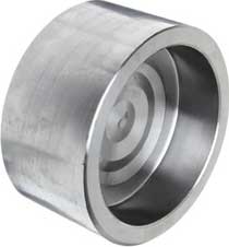
Cap (End Cap)
Dimensions Socket Weld Caps
ASME B16.11
Class 3000 |
||||
| NPS | Socket Bore | Depth Socket | Length Cap | Dia Cap |
| B | J | Q | R | |
| 1/2 | 21.95 21.70 |
10 | 19 | 32 |
| 3/4 | 27.30 27.05 |
13 | 23 | 38 |
| 1 | 34.05 33.80 |
13 | 26 | 45 |
| 1.1/4 | 42.80 42.55 |
13 | 28 | 55 |
| 1.1/2 | 48.90 48.65 |
13 | 30 | 65 |
| 2 | 61.35 61.10 |
16 | 36 | 75 |
| 2.1/2 | 74.20 73.80 |
16 | 38 | 92 |
| 3 | 90.15 89.80 |
16 | 42 | 110 |
| 4 | 115.80 115.45 |
19 | 48 | 140 |
Class 6000 |
||||
| NPS | Socket Bore | Depth Socket | Length Cap | Dia Cap |
| B | J | Q | R | |
| 1/2 | 21.95 21.70 |
10 | 22 | 34 |
| 3/4 | 27.30 27.05 |
13 | 26 | 41 |
| 1 | 34.05 33.80 |
13 | 28 | 50 |
| 1.1/4 | 42.80 42.55 |
13 | 30 | 58 |
| 1.1/2 | 48.90 48.65 |
13 | 32 | 66.5 |
| 2 | 61.35 61.10 |
16 | 38 | 85 |
General notes..
- Dimensions are in millimeters unless otherwise indicated.
- Socket Bore (B) – Maximum and Minimum dimensions.